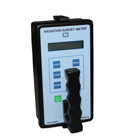
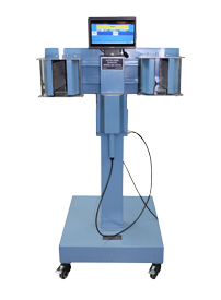
TLD Badge Reader (Navy Version) [ TYPE : TL109D ]
Technical Data

TLD READER SYSTEM Type TL109-D developed and manufactured by NUCLEONIX systems is a personal dosimeter reader system designed to read the dose recorded by the wearer of the TL Dosimeter along with personnel ID punched code on the badge automatically during readout cycle.
This dose is readout from TLD Badge by subjecting each of the TL discs to controlled heating in the instrument and measuring the emitted light using a photo-multiplier tube which is proportional to the integrated dose received by the badge.
The TL dosimeter which records the integrated dose received is to be worn by the personnel who are to be monitored for their radiation exposure, which can be estimated on the basis of the TL Dosimeter readings. TLD dosimeter works on the property of certain materials which absorb energy when exposed to X, a or ? rays. On heating, the absorbed energy is released in the form of visible light which is proportional to the absorbed energy.
TLD Badge: It comprises of a plastic badge and thick aluminium card on which three circular holes are punched and teflon embedded TL discs (CaSo4 : Dy) are chipped into the corresponding holes. A symmetric ?V? cut provided in the card permit the card to be loaded in the plastic badge only in one way and ensure proper positioning of the badge in the magazine. The TLD card is provided with three rows of punched holes for the purpose of badge identification. The holes punched in a specified sequence to provide unique ID to each of the personnel. This ID is read out by the TLD Reader at the time of measurement.
TLD Badge Reader System: The TLD Badge Reader system consists of following subsystems. a. TLD heater unit b. TLD card positioning unit c. TL measuring unit The TL dosimeter card which has to be readout is to be placed on the slot provided on the drawer assembly. On initiating readout through keypad, the individual discs are positioned automatically by the DC motor device system.Now the TLD heater unit, which consists of Kanthal heater is lowered onto the TLD disc by a DC motor and heating is started to heat up the dosimeter to 2800 in 10 sec from room temperature and clamps till measurement is complete.
The measurement and control system comprises of a micro controller based display and logic unit, Photomultiplier Tube, HV supplies and I to F convertor module. The display and logic unit facilitates displaying of various parameters, along with dose for gamma and beta radiation of individual personnel apart from controlling the heating of the Kanthal strip and positioning of the TLD card and heater strip after each readout cycle. The unit also facilitates communication with central computer through RS-232 and RS422C using proprietory protocol.This product finds use in checking Radiation dose exposure of Emergency response teams engaged in tackling nuclear disaster, emergency teams etc. It can be fitted in Hazmat Vehicles and can be deployed anywhere in the field.
Specifications
| Heater Element: | Kanthal / SS circular, ~ 12mm dia. |
|---|---|
| Temperature Profile : | Non-linear reproducible. |
| Clamping Temperature : | Adjustable from 260?C to 290?C. |
| Light Detection : | R6095 or equivalent. |
| PMT Supply : | -500V to -1200V (Adjustable). |
| Reading cycle time : | 60 secs. |
| Exposure Range : | 0.01 R to 1000 R |
| Readout Accuracy : | ? 30% to 100 mR, ?10% above 1R |
| Warm-up Time : | 30 minutes |
| Instrument Operation : | Continuous, round the clock. |
| Background : | <50mR |
| Display : | 4 line LCD (backlit) to display EHT, CAL FACTOR, TEMPERATURE, ID, D1, D2 & D3 data, Reader status, Reader fault, Mode of operation. |
Operating Sequence :
a.Operator places the TLD badge in the drawer.
b. Operator initiates the readout cycle through front panel keypad. (?Start? key)
c. The TLD card positioning unit now drives the TLD card using DC motors. The ID No. on the card is read serially and then the card is positioned to read the three dosimeters one by one.
d. After positioning the dosimeter in front of the PMT the heater strip is raised onto the TL disc by a suitable actuator. The heater is provided with adjustable spring action for optimum pressure on dosimeter.
e.Heating of the TL disc is initiated to a set temperature in the range of 260-290o C for a programmed duration (60 secs).
f. The integral TL intensity emitted by the disc is measured and displayed.
g. The next disc is positioned after the readout and the heating and readout cycles are repeated for the third dosimeter.
h. Dose data of the three discs along with personal ID is stored in the internal memory for subsequent. Reporting / transfer to PC. Data storage for 100 cards is provided.
i. In addition, the dose data is also stored every sec during the readout process for the purpose of plotting the glow curve.
Self Diagnostics :
a. Built-in blue LED light source for instrument stability check.
b. TLD Badge punched code identification no check.
c. LV and HV power supplies check.
d. Heater check e. Mechanical failure check.
Modes of operation :Instrument has three modes of operation
a. Stand-alone Measurement mode
b. Online PC mode
c. Test mode
Internal :A blue LED is switched on for the light path check.
External :Light source (Ni 63 plastic scintillator) in a card is to be inserted and checked.
Controls : ?SET? ?Digit select ?? ?Increment ?? & ?Enter? keys for entering / modifying the parameters. EHT, cal factor, operation mode selection, etc. In addition, the keys can be used to browse the stored data.If the PW is correct, the parameters are displayed as below and they can be altered using ?, ? ?enter keys?. On pressing the ?SET? key repeatedly one of the parameters ?EHT?, ?C.F?, ?Mode?, ?Recall? can be selected. The display indicates the current value
Material Construction : Cast aluminium alloy of suitable grade to meet requirements of strength, vibration and shock.
Connectors : Connectors suitable for marine applications shall be used and will be adopted after approval of customer.
Environmental Specifications :
As per JSS55555 (N2) for Ship borne applications.
a. Low Temp : 0o C
b. Dry Heat : 40o C
c. VIBRATION TEST
d. SHOCK TEST
e. Humidity : 45oC, 95% RH, 16Hrs
EMI / EMC Tests :
As per MIL-STD-461E
a. Conducted Emissions i) CE 01 ii) CE 03
b. Conducted Susceptibility i) CS 01 ii) CS 02 iii) CS 06 iv) CS 09 v) CS 10
c. Radiated Emission Tests i) RE 01 ii) RE 02 iii) RE 03
d. Radiated Susceptibility i) RS 01 ii) RS 02 iii) RS 03 iv) RS 05 v) RS 06
Operation:On pressing the ?SET? key the display indicates ?Password : 0000?. The ?, ?, controls are to be used to set the password and ?enter key? is pressed. In case the PW is wrong, the display indicates ?PW mismatch? and reverts to the normal mode of display
Power Supply:Instrument is powered by 220VAC single phase with a frequency of 400 Hz. The nominal power consumption is <300VA.
Dimensions:It will be within the specified limits.


